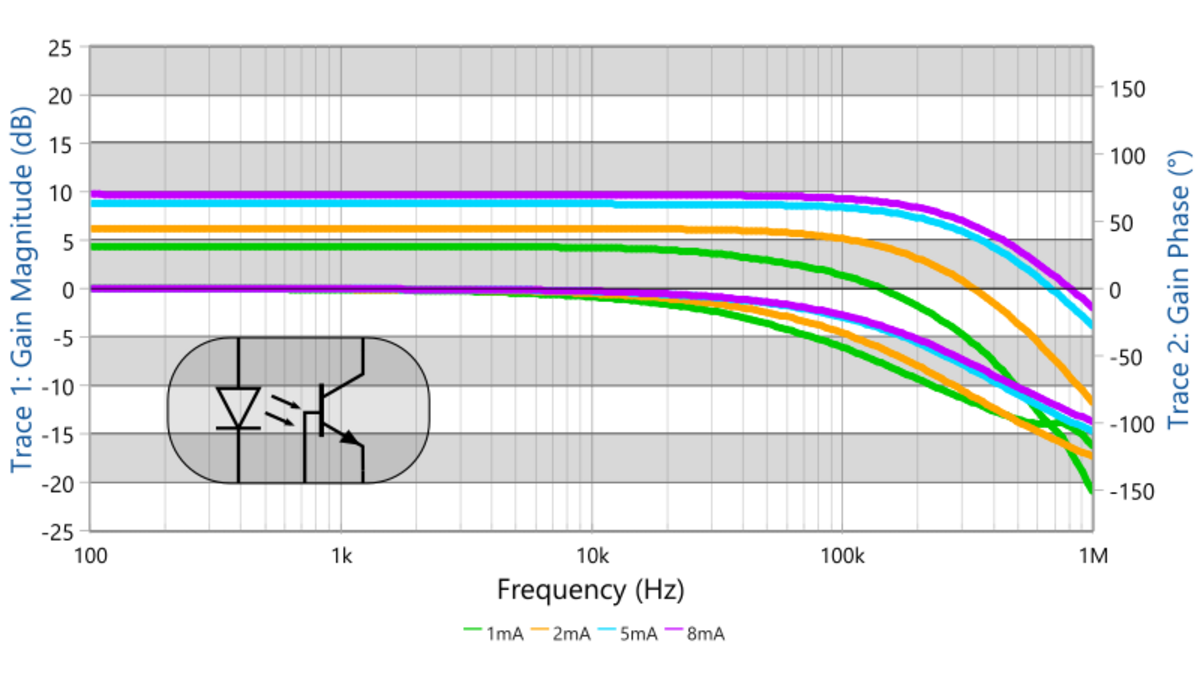
Many power supplies use optocouplers in the feedback loop. The stability and overall performance often depend on the CTR of the optocoupler. CTR curves over frequency are normally not provided by the manufacturer.
On this website, you can find two application notes on how to measure the CTR over frequency.
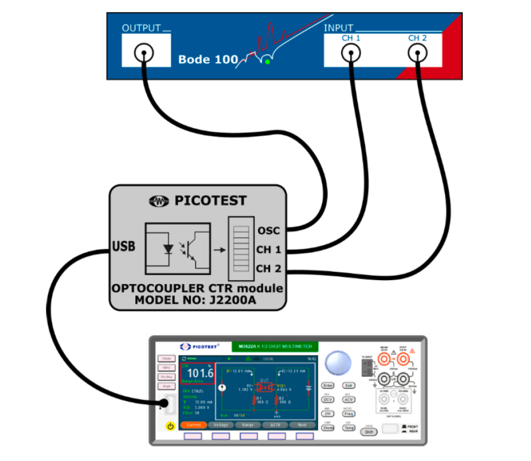
The first document shows a very convenient measurement method using the Bode 100 in conjunction with the Picotest M3522A multimeter and the J2200A optocoupler CTR module. The J2200A from Picotest allows a simple connection, and in combination with the M3522A, it can easily measure absolute and relative CTR by pressing a few buttons.
The second document shows how the CTR can be measured over frequency using the Bode 100 in conjunction with the Picotest J2130A DC Bias Injector.
Check out the application notes by downloading the PDF files: