Electronic devices become smaller and smaller. Multiple supply voltage levels need to be maintained at very high converter efficiencies with fast recovery speed. Switching frequency tends to increase to make things smaller but also addy complexity to system models and design.
In order to ensure the stability of voltage regulators and switched mode power supplies the control loop behavior needs to be characterized not only in simulation but also in real life measurements. The Bode 100 can easily be used to measure gain margin and phase margin of electronic control loops in a frequency range from 1 Hz to 50 MHz. Knowing your system gain margin and phase margin gives you the certainty that your system will be stable even under changed circumstances.
To learn how to use the Bode 100 to measure the loop gain of a buck converter, please download the applcation note:
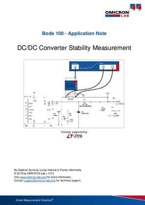
DC/DC Converter Stability Application Note
(2 MB)
Download
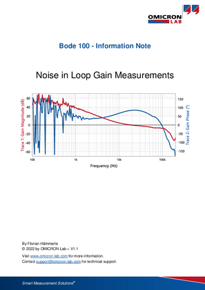
Loop gain measurements can be sensitive to noise, especially at low frequencies. Check out this document to learn why and how to best fight noise for a clean measurement result.
Noisy Loop Measurements - Information Note
(825 KB)
Download
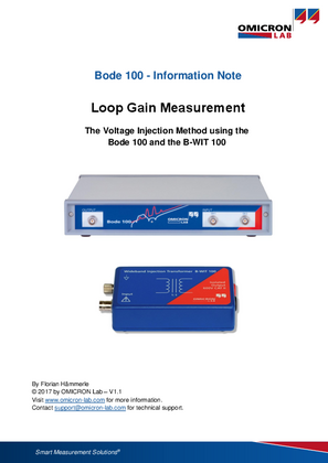
The measurement method for loop gain measurements based on voltage injection was first presented by R.D. Middlebrook in 1975 in the paper "Loop Gain Measurements in Feedback Systems". If you are interested in the math behind the method, check out the following document describing the details behind this simple and elegant measurement method:
Loop Gain Measurement - Information Note
(615 KB)
Download
We try to constantly improve our application notes and videos. To do so, we are happy to receive your valuable opinion on them. Therefore, please send us your comments and insights via the feedback form, which you can access via the button below.
Feedback